
Lathe Machine Parts and Functions | Complete Guide for DAE Mechanical
Learn lathe machine parts and functions with diagrams, operations, and safety tips. A complete, exam-focused guide for DAE Mechanical students.
By Mr. Faisal Rehman8 min read
Introduction — The Lathe Machine: Foundation of Mechanical Machining
The lathe machine is one of the oldest and most important machine tools in mechanical engineering. Often called the "mother of machine tools", it is widely used in workshops, training institutes, automotive plants, and manufacturing industries to shape materials with high precision. For DAE Mechanical Engineering students in Pakistan, the lathe machine is not just an exam topic — it is a core practical skill that defines workshop competence and employability.
From turning simple cylindrical shafts to cutting precision threads, almost every machining concept builds on the lathe. This comprehensive guide explains lathe machine parts and functions, working principle, operations, industrial applications, maintenance procedures, and safety rules in a clear, exam-oriented, and industry-relevant format for 2025.
Related: Building on lathe skills? Explore our guides on CNC Programming for DAE Mechanical and Mechanical Workshop Tools and Their Uses.
Importance of Lathe Machine in Mechanical Engineering and DAE Training
The lathe machine is called the mother of machine tools because many advanced machining centres, milling machines, and CNC systems evolved directly from its basic working principle. Its importance for DAE students spans both academic exams and real-world industrial skills:
- Essential for DAE Mechanical diploma practical examinations and workshop assessments
- Used to manufacture cylindrical, conical, and symmetrical parts found in every industry
- Builds strong fundamentals of cutting speed, feed rate, depth of cut, and tool geometry
- Directly applicable in repair workshops, production plants, tool rooms, and fabrication units
- Knowledge of lathe operations is a minimum requirement for most mechanical workshop jobs in Pakistan and the Gulf
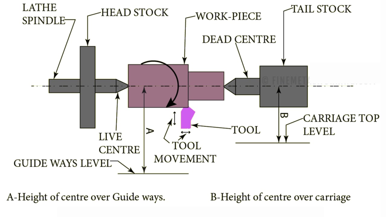
Working Principle of a Lathe Machine — Rotation and Single-Point Cutting
The working principle of a lathe machine is based on a simple but powerful concept: the workpiece rotates about its own axis while a single-point cutting tool is fed into the rotating work to remove material and produce the desired shape and size.
This combination of controlled rotation (spindle speed) and precise tool movement (feed and depth of cut) enables the lathe to perform a wide range of operations — from straight turning and facing, through taper turning and thread cutting, to drilling and boring — all on the same machine.
| Parameter | Definition | Unit |
|---|---|---|
| Spindle Speed | Rotational speed of the workpiece | RPM |
| Cutting Speed | Speed at which the tool cuts the material surface | m/min |
| Feed Rate | Distance tool advances per revolution | mm/rev |
| Depth of Cut | How deep the tool penetrates the workpiece | mm |
Main Parts of a Lathe Machine — Labeled Diagram and Overview
A standard centre lathe consists of several major components. Each part is designed for rigidity, accuracy, and smooth operation. The diagram below shows their positions, followed by individual explanations:
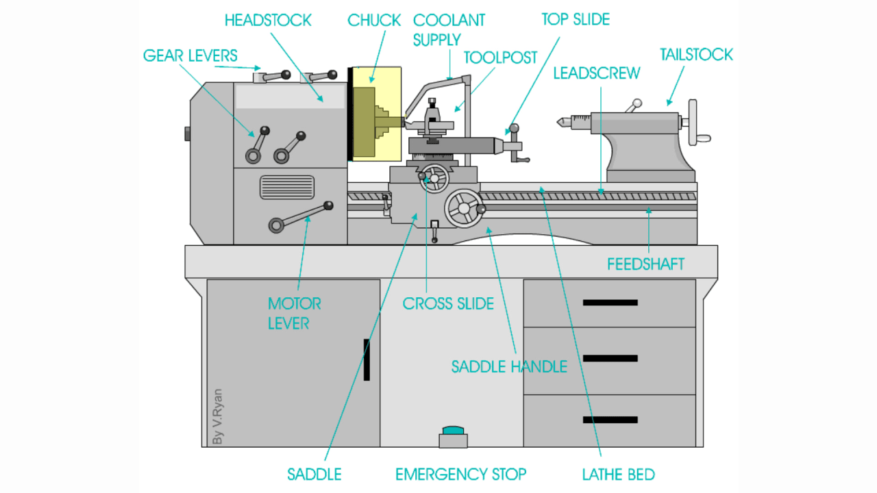
Headstock
PartHouses the main spindle, gearbox, and speed-change mechanisms. Mounts on the left side of the bed.
Tailstock
PartSupports long workpieces and holds drilling or reaming tools. Located on the right side of the bed.
Carriage
PartMoves the cutting tool along and across the workpiece. Contains cross slide, compound rest, tool post, and apron.
Lathe Bed
PartThe rigid cast-iron base that supports all components and maintains precision alignment throughout operation.
Feed & Lead Screws
PartControl automatic carriage movement for smooth turning (feed screw) and accurate thread cutting (lead screw).
Chuck / Faceplate
PartHolds and grips the workpiece securely during rotation. Three-jaw and four-jaw chucks are most common.
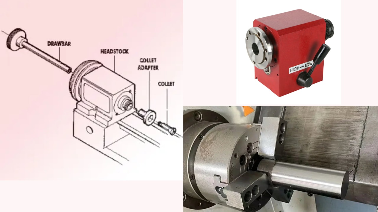
Headstock — Main Spindle, Gearbox & Chuck Functions
The headstock is mounted on the left end of the lathe bed. It is the power unit of the lathe — housing the main spindle, gearbox, speed-changing mechanisms, and the chuck or faceplate that grips the workpiece.
Key components of the headstock
- Main spindle: Hollow shaft that rotates the workpiece — has a Morse taper bore to accept centres and mandrels
- Gearbox / back gear: Provides multiple speed ranges and increases torque for heavy cuts
- Chuck (3-jaw or 4-jaw): Grips round, square, or irregular workpieces securely
- Faceplate: Used for irregularly shaped workpieces that cannot be held in a chuck
- Speed selector levers: Change spindle RPM to match the material and operation
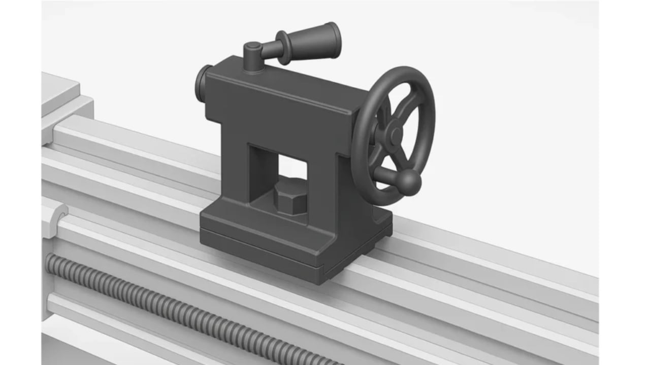
Tailstock — Supporting Long Workpieces and Drilling Operations
The tailstock is located on the right end of the lathe bed and can slide along the bed ways to any position. It serves two main purposes: supporting long workpieces to prevent deflection, and holding tools such as drills, reamers, and taps for axial machining operations.
Key functions of the tailstock
- Dead centre / live centre: Supports the free end of long shafts to maintain alignment during turning
- Drill chuck: Holds drills, reamers, and taps for drilling operations on the lathe
- Tailstock spindle (quill): Advances axially via a handwheel to feed drilling tools into the workpiece
- Offset capability: Tailstock can be offset laterally to enable taper turning between centres
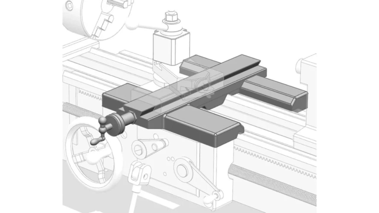
Carriage — Cross Slide, Compound Rest, Tool Post & Apron
The carriage is the assembly that holds and moves the cutting tool precisely along and across the workpiece. It slides along the bed ways and is responsible for both longitudinal (Z-axis) and cross (X-axis) tool movements. The carriage has four main sub-assemblies:
| Sub-Assembly | Function |
|---|---|
| Saddle | Rides on the bed ways and supports the entire carriage assembly |
| Cross Slide | Moves the tool perpendicular to the bed axis (in/out) for facing and depth of cut |
| Compound Rest | Swivels at any angle for taper turning and tool angle setting |
| Tool Post | Clamps and positions the cutting tool; quick-change tool posts allow fast tool changes |
| Apron | Contains the clutches, gears, and handwheels that control carriage movement and engage the feed/lead screw |
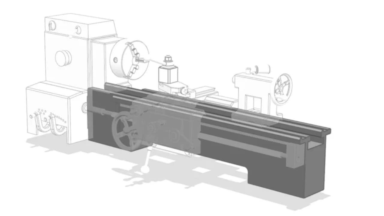
Lathe Bed — Rigid Base Structure and Alignment Guide
The lathe bed is the heavy, rigid cast-iron base that forms the foundation of the entire machine. All major components — headstock, tailstock, and carriage — are mounted on or guided by the bed. Its rigidity directly determines the accuracy of the entire machine.
- Bed ways (guide ways): Precision-machined flat or V-shaped surfaces along which the carriage and tailstock slide
- Material: Close-grained cast iron, sometimes hardened and ground for wear resistance
- Purpose: Maintains precise alignment between headstock, tailstock, and carriage throughout all operations
- Size: Bed length determines the maximum workpiece length that can be machined (swing over bed)
Feed Screw and Lead Screw — Automatic Carriage Movement & Thread Cutting
The feed screw and lead screw run parallel to the bed along its full length and are driven by the headstock gearbox. Together they control the automatic movement of the carriage — eliminating the need for manual handwheel operation during turning and threading.
Feed Screw (Rod)
- Provides smooth, consistent automatic feed for turning and facing
- Used for general turning operations where thread accuracy is not required
- Controlled via the apron half-nut lever and feed selector
Lead Screw
- Provides precise, synchronised movement for accurate thread cutting
- Pitch of lead screw determines threads per inch or mm that can be cut
- Engaged via the half-nut mechanism in the apron for threading passes
Common Lathe Machine Operations — Turning, Threading, Drilling & More
The lathe machine can perform a wide range of machining operations using different tool types, speeds, feeds, and setups:
| Operation | Description | Purpose |
|---|---|---|
| Turning | Removing material from the outer diameter | Reduce diameter to required size |
| Facing | Cutting the end face perpendicular to the axis | Produce a flat, smooth end surface |
| Thread Cutting | Using lead screw to produce helical threads | External and internal threads on shafts and bores |
| Drilling | Feeding a drill via the tailstock into the rotating work | Produce holes along the workpiece axis |
| Taper Turning | Producing a conical surface using compound rest or tailstock offset | Shafts with tapered ends (Morse tapers) |
| Knurling | Pressing a knurling tool to produce a patterned surface | Grip surfaces on handles and knobs |
| Boring | Enlarging an existing hole with a boring bar | Accurate internal diameter machining |
| Parting / Grooving | Cutting a groove or separating the workpiece | Undercuts, recesses, and parting off finished parts |
Industrial Applications of Lathe Machine in Pakistan and Globally
The lathe machine is found in virtually every sector of manufacturing and engineering. Its versatility makes it indispensable across these industries:
Automobile Industry
Crankshafts, axles, brake drums, and engine components
Aerospace Components
Precision shafts, landing gear parts, and turbine components
Repair Workshops
Shaft repairs, bushing manufacture, and custom replacement parts
Manufacturing Plants
Mass production of turned components, fasteners, and fittings
Oil & Gas Industry
Pump shafts, valve bodies, and pipeline fittings
Medical Devices
Surgical instruments, implant components, and precision medical parts
Electrical & Electronics
Motor shafts, commutators, and precision housings
Lathe Machine Maintenance and Safety Precautions for DAE Students
Routine maintenance checklist
- Check and top up lubrication oil daily before operation
- Clean swarf (metal chips) from bed ways after every use
- Inspect chuck jaws for wear and replace as needed
- Check belt tension and drive mechanism weekly
- Verify tailstock and carriage alignment monthly
- Inspect lead screw and feed rod for wear and backlash
- Keep electrical connections clean and dry
Safety precautions — never skip these
- Always wear safety glasses and close-toed shoes
- Never touch a rotating chuck, workpiece, or cutting tool
- Remove the chuck key before starting the machine
- Ensure the workpiece is clamped securely before turning on
- Keep clothing and hair away from rotating parts
- Never leave the machine running unattended
- Isolate power before changing tools or measuring
Important: Most lathe accidents occur due to forgetting to remove the chuck key before starting. Always make this a non-negotiable habit from day one of workshop training.
Frequently Asked Questions (FAQs)
- What are the main parts of a lathe machine?
- The main parts of a lathe machine include the headstock, tailstock, carriage, bed, lead screw, feed rod, and spindle. Each part plays a crucial role in machining operations.
- What is the function of the headstock in a lathe machine?
- The headstock houses the main spindle and speed control mechanism. It rotates the workpiece at different speeds required for turning, facing, and threading operations.
- Why is the tailstock used in a lathe machine?
- The tailstock supports the free end of long workpieces and holds tools such as drills, reamers, and taps during machining operations.
- What are common lathe machine operations?
- Common lathe operations include turning, facing, drilling, thread cutting, taper turning, knurling, and boring.
- Why is the lathe machine important for DAE Mechanical students?
- The lathe machine is essential for DAE Mechanical students because it forms the foundation of workshop practice, practical exams, and industrial machining skills.
- What safety precautions should be followed while operating a lathe machine?
- Operators should wear proper PPE, avoid loose clothing, ensure correct spindle speed, keep the machine clean, and never touch rotating parts during operation.
Conclusion — Master the Lathe, Master the Core of Mechanical Engineering
The lathe machine remains the backbone of every mechanical workshop in Pakistan and globally. A deep understanding of its parts, functions, working principle, and operations gives DAE Mechanical students a strong foundation for both academic examinations and real industrial careers.
Master the lathe — its headstock, tailstock, carriage, bed, and screws — and you gain the machining intuition that underpins CNC programming, manufacturing, and advanced engineering roles.
Always practise safe workshop habits from day one. The skills you build on a manual lathe will serve you throughout your entire mechanical engineering career.
Continue learning: Learn CNC Programming · Mechanical Workshop Tools · Best Software for DAE Mechanical Engineers.
Written by
Mr. Faisal Rehman
Mr. Faisal Rehman offers 12 years of experience in mechanical design, energy systems, and industrial machinery. He combines technical rigor with practical innovation in all projects.