
Measuring Instruments in Mechanical Engineering | DAE Mechanical Guide
Accuracy matters in mechanical engineering! Learn about all essential measuring instruments for DAE Mechanical students and how to use them correctly.
By Ms. Syeda Tayyaba Rasheed8 min read
Why Measuring Instruments Matter in Mechanical Engineering
Measurement is the foundation of every mechanical workshop operation. In mechanical engineering, tolerances are measured in fractions of a millimetre — and a deviation of even 0.1 mm can cause a machine part to fail, an assembly to misalign, or a manufactured component to be scrapped entirely. For DAE Mechanical students in Pakistan, mastering measuring instruments is not optional — it is a core workshop competency tested in every practical exam and required in every industrial job.
Without accurate measuring instruments, machines cannot be assembled to specification, performance and safety are compromised, and fabrication errors lead to costly material wastage and rework. Every hour spent learning precise measurement in your first year saves hours of rework in your career.
Precision & Quality
Parts manufactured within tolerance fit, function, and last — parts outside tolerance fail or must be remade.
Safety
Correctly measured and fitted components prevent mechanical failure that can cause injury in operating machinery.
Cost Saving
Accurate measurement prevents scrap material, reduces rework time, and lowers production cost significantly.
Before learning measuring instruments, make sure you are familiar with mechanical workshop tools and their uses and the safety rules in the mechanical workshop.
Linear Measuring Instruments
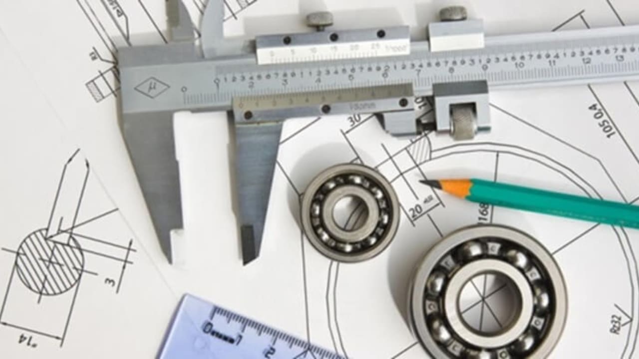
Linear instruments measure dimensions along a straight line — length, width, diameter, and depth. These are the most frequently used measurement tools in any mechanical workshop and the first instruments every DAE Mechanical student must master.
Vernier Caliper
±0.02 mmMeasures internal diameter, external diameter, and depth in one tool. The most versatile and commonly used instrument in the mechanical workshop.
Micrometer Screw Gauge
±0.01 mmProvides the highest precision for small external dimensions. Essential for shaft diameters, bolt measurements, and close-tolerance work.
Steel Rule
±0.5 mmThe most basic linear measuring tool — used for rough measurements, setting out, and general workshop layout work.
Measuring Tape
±1 mmUsed for measuring long distances, large components, and site layouts where a steel rule is too short.
Depth Gauge
±0.02 mmMeasures the depth of holes, slots, recesses, and grooves accurately. Available in Vernier, dial, and digital versions.
Inside Caliper
±0.5 mmTransfers or measures internal dimensions such as bore diameters and slot widths when combined with a steel rule.
Workshop tip: Always zero your Vernier caliper and micrometer before taking any measurement, and ensure both the tool and the workpiece are clean and at room temperature. Temperature expansion in metal can introduce measurement errors in close-tolerance work.
Angular Measuring Instruments
Angular instruments measure angles, slopes, and tapers in mechanical components and machine setups. Correct angular measurement is critical for milling, grinding, gear cutting, and any machining that involves inclined surfaces.
Protractor
±1°Manual angle measurement tool used for marking out and checking angles on workpieces. Basic but essential for layout work.
Bevel Protractor
±5′ (minutes)A precision vernier protractor used for accurate angle measurement in machine setups, tool setting, and component inspection.
Spirit Level
±0.02 mm/mChecks horizontal and vertical alignment of machine beds, surfaces, and components. Essential for machine installation and alignment.
Sine Bar
±±1 secondUses gauge blocks to set up and measure precise angles through trigonometric calculation. Used for very accurate angular inspection.
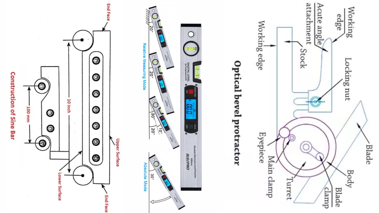
Sine bar tip: The sine bar formula is sin θ = H / L, where H is the gauge block stack height and L is the sine bar length (usually 100 mm or 250 mm). This is a common exam question in DAE Mechanical practical assessments.
Comparative Measuring Instruments
Comparative instruments do not give absolute dimensions — they measure deviation from a known reference or standard. They are used for quality control, checking roundness, detecting runout, and verifying that machined parts meet tolerance specifications.
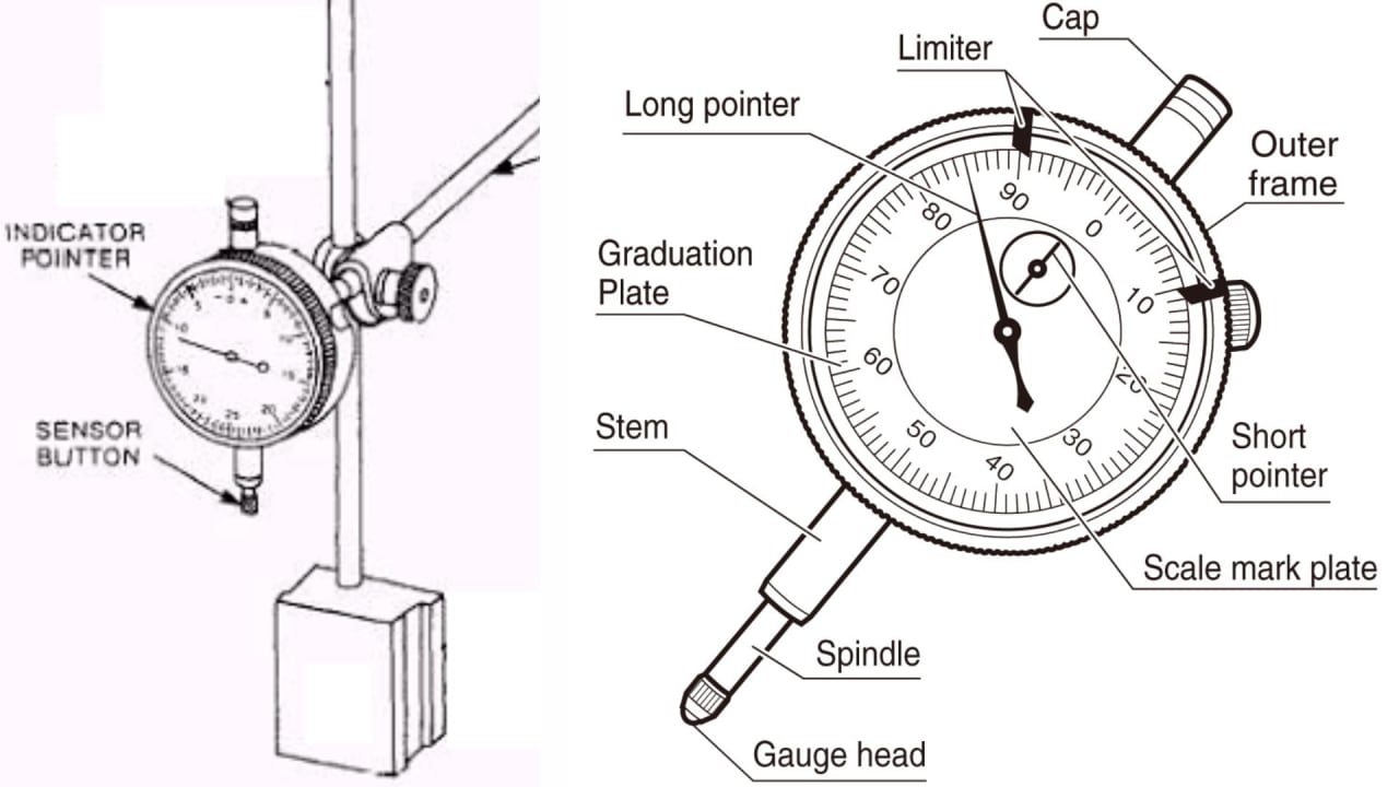
Dial Indicator (DTI)
±0.01 mmDetects small displacements and deviations on rotating or moving parts. Used for checking runout, flatness, and alignment on machine tables and spindles.
Comparator
±0.01–0.02 mmCompares the dimension of a workpiece against a calibrated master gauge. Used in production inspection to accept or reject components rapidly.
Gauge Blocks (Slip Gauges)
±0.001 mmPrecision-ground steel blocks wrung together to form exact reference lengths. Used for calibrating other instruments and setting up comparators.
Feeler Gauge
±0.05 mmA set of thin metal strips of known thickness used to measure small gaps between mating surfaces — gear clearances, valve clearances, and bearing fits.
Comparative instruments — precision at a glance
| Instrument | Primary Use | Precision |
|---|---|---|
| Dial Indicator (DTI) | Detect runout and deviation | ±0.01 mm |
| Comparator | Accept / reject vs master | ±0.01–0.02 mm |
| Gauge Blocks | Calibration reference standard | ±0.001 mm |
| Feeler Gauge | Gap and clearance measurement | ±0.05 mm |
Precision Instruments for Advanced Mechanical Work
Precision instruments are used when standard Vernier or micrometer measurements are insufficient — typically in jig and fixture work, quality control inspection, and tool room operations where tolerances reach micron level.
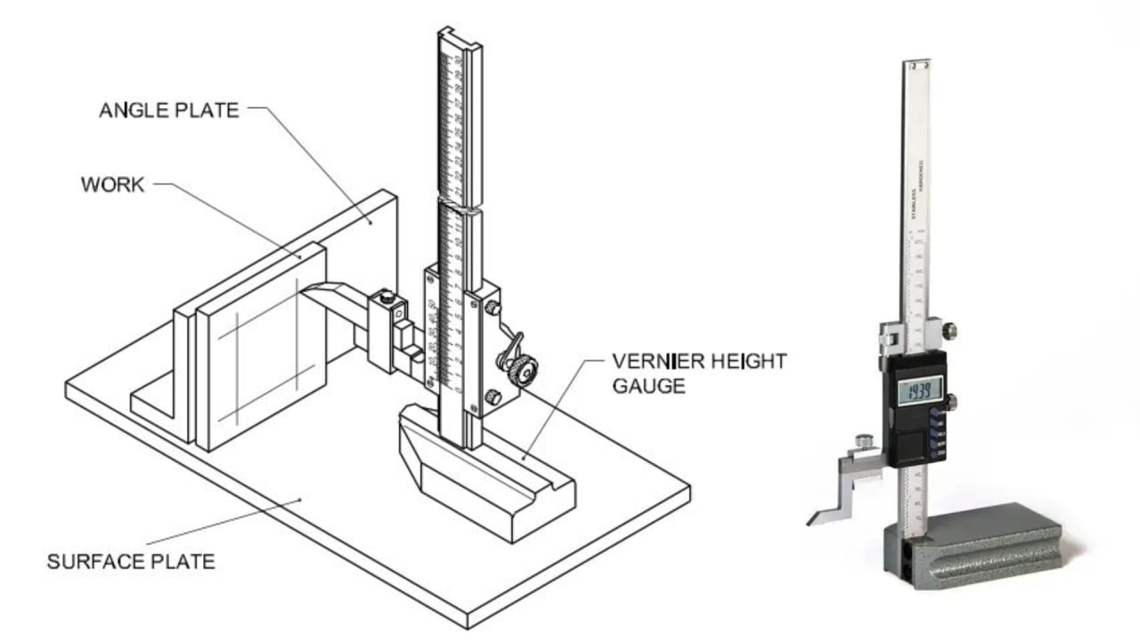
Height Gauge
±0.02 mmMeasures vertical distances from a datum surface plate. Used for layout work, scribing parallel lines, and inspecting machined heights.
Surface Plate
±Grade 0 / 1 / 2A precision-ground flat cast iron or granite reference plane. All height, flatness, and comparator measurements are taken relative to it.
Telescopic Gauge
±0.01 mmTransfers internal bore diameters that are too large for an inside micrometer. The spring-loaded plunger locks at the bore diameter, then measured with a micrometer.
Outside Micrometer
±0.01 mmThe most precise hand tool for measuring external shaft diameters, bolt ODs, and plate thickness. Available in ranges of 0–25 mm, 25–50 mm, etc.
Inside Micrometer
±0.01 mmMeasures internal diameters of bores, cylinders, and holes with micrometer precision — where a Vernier caliper jaw would not reach accurately.
V-Block & Clamp
±Reference fixtureHolds round workpieces securely on the surface plate for checking roundness, runout, and concentricity with a dial indicator.
Surface plate care: Never place tools or workpieces roughly on a surface plate — even a small nick or scratch permanently destroys the reference accuracy. Always wipe clean with a lint-free cloth before and after use.
Digital & Modern Measuring Instruments
Digital instruments offer the same measurement function as their analog counterparts but eliminate human reading errors, provide instant digital readout, and often include data-logging and metric/ imperial switching. Modern workshops increasingly use digital tools alongside traditional analog instruments.
Analog Instruments
Traditional — Learn First
- Builds reading skill and understanding
- No battery dependency
- More durable in harsh workshop environments
- Required for most DAE exams and assessments
Digital Instruments
Modern — Industry Standard
- Instant, error-free digital readout
- Metric / imperial switching at a button
- Data logging for quality records
- Preferred in modern manufacturing and QC
Key digital instruments for DAE Mechanical students
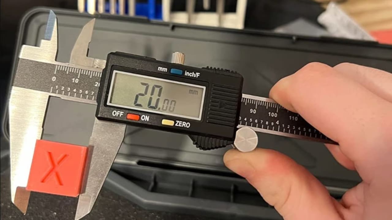
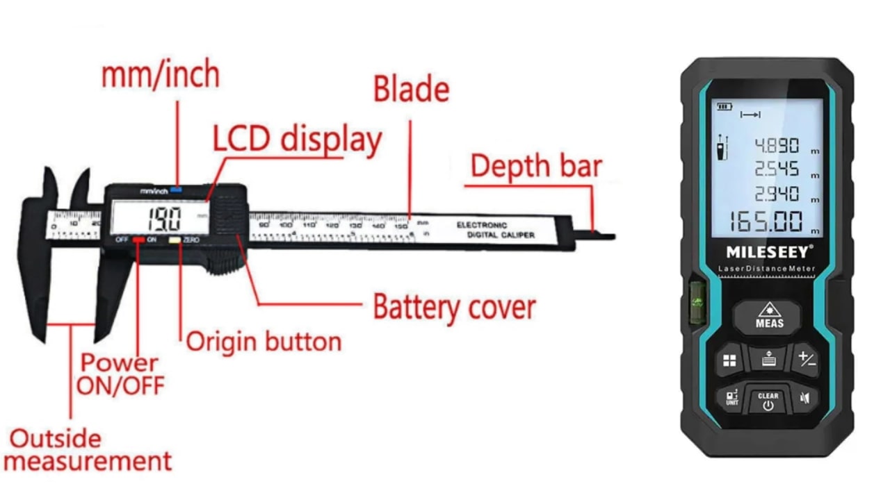
Digital Vernier Caliper
±0.01 mmProvides instant digital readout of internal, external, and depth measurements. Eliminates Vernier reading errors — ideal for high-speed inspection.
Digital Micrometer
±0.001 mmSame function as a standard micrometer with digital display. Removes the need to read the thimble scale — improves speed and consistency.
Laser Distance Meter
±±1 mmMeasures long distances (up to 100 m+) using laser reflection. Used in construction, facility layout, and large component measurement.
Coordinate Measuring Machine (CMM)
±±0.001 mmAutomated 3D measurement of complex components using a precision probe. The industry standard for dimensional inspection of machined parts.
Learning order: Always learn to read analog instruments first — Vernier scale, micrometer thimble, and dial indicator. Once you understand the underlying measurement principle, switching to digital is trivial and takes minutes. Skipping analog practice creates a knowledge gap that causes errors when digital tools are unavailable.
Which Instrument for Which Task?
Choosing the correct measuring instrument for a task is as important as using it correctly. This quick-reference guide covers the most common workshop measurement scenarios.
Measure a shaft external diameter
Outside MicrometerHighest accuracy for external cylindrical dimensions — more precise than Vernier caliper jaws on round surfaces.
Measure a bore internal diameter
Telescopic Gauge + MicrometerThe telescopic gauge transfers the bore size; the micrometer reads it. Inside micrometer used for larger bores.
Check a machined part against a tolerance
Dial Indicator / ComparatorComparator instruments detect deviation from a master reference — faster and more reliable than re-measuring each part.
Set up an angle on the milling machine
Bevel Protractor or Sine BarBevel protractor for angles to 5 minutes; sine bar + gauge blocks for extreme precision to 1 second of arc.
Check machine table / bed alignment
Spirit Level + Dial IndicatorSpirit level confirms horizontal/vertical; dial indicator swept across the bed detects twist and taper.
Measure hole or slot depth
Depth Gauge (Vernier or Digital)Depth gauge is purpose-built for this — far more accurate than attempting to measure depth with caliper jaws.
Check valve clearance or gear backlash
Feeler GaugeFeeler gauge strips are the only practical way to measure thin clearance gaps between mating mechanical surfaces.
Tips for Using Measuring Instruments Correctly
Even the most expensive measuring instrument produces wrong results if used incorrectly. These five habits separate a precise craftsman from an amateur — and are directly assessed in DAE Mechanical practical exams.
Always Calibrate Before Use
Zero your Vernier caliper, micrometer, and dial indicator before every measurement session. Never assume an instrument is correctly zeroed from the last user.
Clean Tools and Workpieces
Oil, swarf, and dust on either the instrument or the workpiece introduce measurement errors. Wipe both with a clean cloth before measuring.
Handle Delicate Instruments Carefully
Never drop a micrometer, bang a dial indicator, or store Vernier calipers loose in a drawer. Damage to measuring faces is irreversible and ruins accuracy.
Record Measurements Systematically
Write measurements down immediately — do not rely on memory. In quality inspection and project work, undocumented measurements have no value.
Cross-Check Critical Dimensions
For dimensions that affect fit or function, take the measurement three times and use the average. Use a second instrument type to confirm if possible.
Exam tip: In DAE Mechanical practical assessments, examiners specifically watch whether you zero the instrument, clean the workpiece, and take the measurement at the correct position. These procedural steps carry marks — not just the final numerical reading.
Frequently Asked Questions (FAQs)
- What is the most commonly used measuring instrument in mechanical workshops?
- The Vernier Caliper is the most versatile and widely used for internal, external, and depth measurements.
- How do I measure the diameter of a hole accurately?
- Use a Telescopic Gauge with a micrometer or an inside micrometer for precise internal measurements.
- Are digital measuring instruments better than manual ones?
- Digital tools provide faster, easier, and more accurate readings, but manual tools are still essential for basics.
- Can these instruments be used for final year projects?
- Yes, accurate measurement is critical for prototypes, mechanical models, and assembly tasks.
- How should I maintain measuring instruments?
- Clean, store in protective cases, calibrate regularly, and avoid dropping or mishandling them.
Conclusion — Master Measuring Instruments for Mechanical Precision
Measuring instruments are the link between engineering drawings and physical reality. A dimension on a drawing is only achieved when the machinist can measure it accurately — and that requires the right instrument, used correctly, every time.
From the Vernier caliper and micrometer to the dial indicator, sine bar, and CMM — each instrument has a specific role. Master the fundamentals first, understand when to use each tool, and build the calibration and care habits that define a precise mechanical engineer.
Combine strong measuring skills with practical workshop knowledge, lathe and machine operation, and software skills — and you will be genuinely job-ready as a DAE Mechanical graduate in Pakistan.
Continue learning: Pair your measurement skills with mechanical workshop tools, lathe machine parts and functions, and safety rules in the mechanical workshop for complete practical mastery. For final-year projects, explore our DAE Mechanical final year project ideas.
Explore more engineering guides in our articles section.
Written by
Ms. Syeda Tayyaba Rasheed
Ms. Syeda Tayyaba Rasheed has 11 years of experience guiding students through laboratory experiments, materials testing, and equipment handling. She emphasizes precision, methodology, and practical application of engineering and architectural principles.